It’s been two years the last time I update this blog. WordPress almost delete the blog. Thankfully I can update now. I notice that there are people who were having problems in purchasing the macro. I’ll update soon.
IsoPro – Speed up your Isometric drawing extraction
Current isometric extraction process:
1. Go to isodraft
2. Select the pipe
3. Extract the isometric and produce .plt files and .dxf files
4. Convert to PDF files from dxf files
5. Repeat the process for other pipes
What can IsoPro do to help you:
1. Extract the isometric drawings in Design module
2. Automatically produce isometric drawings in PDF
3. Multiple pipes extracted at one time
4. Option to produce dxf, matreial and bolt files
Screen shot:

Price:
$50
Download here:
![]()
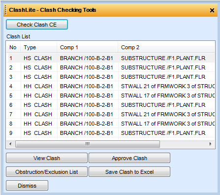
ClashLite – Clash Checking Utility
Price:
$40
Download the macro here
![]()
It can:
1. Check clashes of elements such as Pipe, Equipment, Structure and other Design elements
2. View the clashes in the 3D view
3. Approve the clashes and the approved clashes would not appear in the next clash checking process
4. Save the clashes in to clash report in Excel format
How to use it:
1. Copy the PDMSMACRO folder into PMLLIB folder
2. Go to design module and type PML REHASH ALL and then type SHOW!!CLASH
3. After the form appears, navigate CE to Pipe or structure or any other element you want to check for clashes. Then press ‘Clash Check CE’ button
4. The clash list will appear in the form

5. Select element you want to check for clashes and press Check Clash for CE button
6. The clashes will appear in the Clash List
7. Select the clash you want to view and then press View Clash Button
8. The 3D View will automatically shows you the clashing items and will be highlighted

9. Press Approve Clash button to approve the false clash. Resolve the clash if it’s a real clash
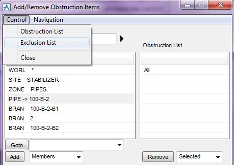
10. Press Obstruction/Exclusion List to add elements you want to exclude during clash checking to minimize you clashes
11. After approving and resolving the clashes, you need to check again for clashes by pressing the Check Clash CE button
12. You can also export the clashes into clash report in Excel format by pressing Save Clash to Excel button

Download the macro here
![]()
SDNFPro – PDMS / SDNF Integration (Export and Import)
What is SDNFPro?
SNDFPro is PDMS tools to export structural sections and panels from PDMS to SDNF and converting SDNF file to PDMS structural sections and panel
What is SDNF?
SDNF or Steel Detailing Neutral Format file is a standard format for transferring structural data from different software.
Can we export and import SDNF file without SDNFPro?
Yes, you may purchase Aveva Open Steel for $1.000 a month. Please contact Aveva sales. You also need to do the setup before using Open Steel
How much time to set up SDNFPro?
No setup required (no need UDA creation, no need to change the profile catalogues)
Can SDNFPro export Structural member to SDNF file?
YES
Can SDNFPro import Structural member to PDMS?
YES
How much does it cost ?
$50
Why is it not FREE?
Well….SDNFPro is created by a human being
How to download?
Press the button below
![]()
OR
![]()
Screen Shots

PDMS Model

Tekla model

How to Activate ASL Modeller in PDMS version 12
1. Search this folder
C:\AVEVA\Plant\PDMS12.0.SP6\PDMSUI\des\addins\
2. Open file named ACCESS and edit
3. Remove the hash character (#) such that the content becomes:
# ———————————————————————-
#
# (c) Copyright 2004 to Current Year AVEVA Solutions Limited
#
# File: ACCESS
# Type: Add-in Definition
# Module: design
#
# Author: Jamie Brunning
# Created: Wed Jun 03 16:17:00 2004
#
#
#
# Description: Add-in definition for ASL Modeller application
#
# ———————————————————————-
#
name: ACCESS
directory: ACCESS
showOnMenu: TRUE
object: APPACCESS
title: ASL Modeller
callback: CALLAC IACCEAPP SCTN
group: 1
groupName: Structures
synonym: CALLAC
startUp: $M “%PDMSUI%\DES\ACCESS\INIT”
helpAlias: DRMPCM
PDMS Macro for generating COG report

This macro works this way
1. First you need to create a box for area to be selected in COG report. This box can be enclosing a deck, an area or the entire model. Set this box in the Clip Box.
2. Set the hierarchy you want to include in the report. This hierarchy can be the entire model, a site or a zone. If you want to include more than 1 site, first you need to create a GPSET (group set) and add the sites.
3. Create a box or an equipment as the COG origin. Position the COG origin in the correct location. All COG will be taken with respect to the COG origin set in this column.
Run the report and you will get the weight for the area. For components that have missing cmpref will be reported in a file.

To download, click button below. Warning, it is not free.

A look at Aveva Everything 3D (E3D)
Succesfully installed Aveva E3D. This is the snapshot taken from Design module of Aveva E3D.
These are my first impressions:
1. The ribbon toolbar is confusing and lots of buttons need to memorize.
2. The shading of the model is better.
3. I love that we still have the command window and do Q ATT

Failed isometric in Design
Options file problem: (2,752) Array element 2 does not exist
(33,148) PLOT FILENAME PREFIX has not been specified
Whenever we extract iso from design module, if there is previewisostd.txt file in the project xxxiso std folder
then it looks for it first rather than looking for C:/aveva/plant/——-/pdmsui/dflts/std
I have deleted previewisostd.txt from the project folder, so now it looks for the default pdms path and its working fine
Creating a Top Level Element in a Specific Database
To create a new top level element in a specific database there is a DB keyword available in the syntax of the ‘NEW’ command as follows:
NEW element_type element_name DB database_name
where element_name is again optional and where the database_name is expressed as a fully qualified database name, i.e. team/database.
The following command will create a new SITE named /MYSITE in the MYTEAM/MYDB database.
NEW SITE /MYSITE DB MYTEAM/MYDB
New blog created: SP3DWorld
Feel bored to learn only PDMS? Start to learn SmartPlant 3D in the new blog
SP3DWorld.wordpress.com
The blog start with the complicated SP3D Installation guide located here
By PDMSMacro
